


The Bosch AFC Digifant system is a computer-controlled fuel injection system. The system does not use cold start injector or thermo time switch for cold start enrichment. Different sensors and switches, along with Electronic Control Unit (ECU), regulate fuel injection and ignition timing.
It Uses two cpu's, One is a MAF80A39 (Intel 80A39) and another Motorola Cpu for DSP.

Digifant II was the secondin a line of Digifant injection systems (Digijet was Volkswagen's first electronic injection system, then Digifant I, which is very similar to Digifant II, were both used on the Vanagon in the early 80s). Unlike Digijet, it integrates digital ignition control as well. It is full electronic, and uses individual electronically controlled injectors, which are batch-fired. It has integrated fault memory and diagnosis, and was equipped with an OBD fault warning light in California models before the more emissions-specific Digifant I was released. Digifant II receives information from the hall generator (provides engine speed), the air flow sensor (provides engine load), the coolant temperature sensor, the air intake temperature sensor, the oxygen sensor, basic throttle position, and the knock sensor to adjust the fuel/air mixture.

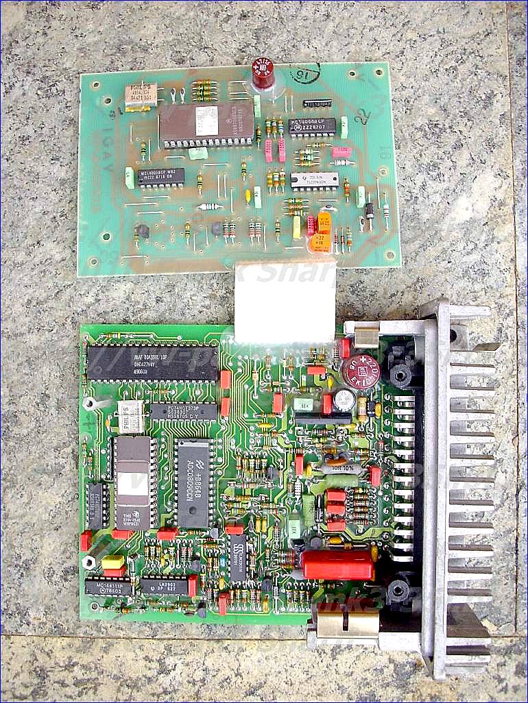
Electronic Control Unit BOSCH DIGIFANT 2 0 261 200 298 037906022N DF1.
The ECU controls all engine operations, and limits maximum engine speed. It receives information from various input devices.
The ECU is a micro-computer. It is constructed from printed circuitry, and contains a large number of electrical components, including many semiconductor devices.
Its input devices receive data as electrical signals. They come from sensors and components at various locations around the engine. Its processing unit compares incoming data with data stored in a memory unit. The memory unit contains basic data about how the engine is to operate. And an output device pulses the electrical circuit of the solenoid-type injection valves.
It is normally located in a safe place, behind a kick-panel in the foot-well, under the passenger seat, or in the boot, and connected by a multi-plug, or plugs, to the vehicle’s wiring harness.
 The core function of a basic ECU in an EFI system is to control the pulse width of the injector. More sophisticated models also control other functions such as idle speed, ignition timing, and the fuel pump. These wider systems are called engine management systems. The more precise control they allow is very effective in reducing fuel consumption and exhaust emissions.
The ECU adjusts quickly to changing conditions by using what are called programmed characteristic maps, stored in the memory unit. They are programmed into the ECU, just as data is programmed into a computer. Characteristics means the engine’s operating conditions. And they are called maps because they map all of the operating conditions for the engine.
They are constructed first from dynamometer tests, then fine-tuned, to optimise the operating conditions and to comply with emission regulations. This data is stored electronically.
Ignition timing is crucial in this process. Between one spark and the next, the ECU uses data it receives on engine load and speed to determine when the next ignition point will occur. It can also correct the map value, using extra information such as engine coolant temperature, intake air temperature, or throttle position. Putting all of this together, it arrives at the best ignition point for that operating condition.


VOLKSWAGEN PASSAT ENGINE CONTROL MANAGEMENT DIGIFANT 2 CIRCUITS DESCRIPTIONS:
MAB8039H L MAF80A39: SINGLE-CHIP 8-BIT MICROCONTROLLER:
ROM-less version of the MAB8049H
The MAB80XXH family of single-chip 8-bit microcontrollers is fabricated in NMOS.
These microcontrollers are designed to be efficient control processors as well as arithmetic processors.
Their instruction set allows the user to directly set and reset individual l/O lines as well as testindividual bits within the accumulator. A large variety of branch and table look-up instructions enable
efficient implementation of standard logic functions. Code efficiency is high; over 70% of the
instructions are single byte; all others are two byte.
The counter can be used to generate an interrupt to the processor.
Program and data memories plus input/output capabilities can be expanded using standard TTL
compatible memories and logic.
Features
8-bit CPU, ROM, RAM and l/O
8-bit counter/timer
On-chip oscillator and clock driver circuits
Single-level interrupts: external and counter/timer
17 internal registers: accumulator, 16 addressable registers
Over 90 instructions: 70% single byte
All instructions 1 or 2 cycles
Easily expandable memory and 27 l/O lines
TTL compatible inputs and outputs
Single 5 V supply
Standard and extended temperature ranges : MAB80XX: 0 to +70 °C
MAF80XX: -40 to +85 °C
MAF80AXX: ~40 to +110 °C
Applications:
Peripheral interfaces and controllers 0 Modems and data enciphering
Test and measuring instruments 0 Environmental control systems
Sequencers 0 Audio/video systems, ENGINE CONTROL MANAGEMENT !!
ADC0808/ADC0809 8-Bit µP Compatible A/D Converters with 8-Channel Multiplexer:
General Description
monolithic CMOS device with an 8-bit analog-to-digital converter,
8-channel multiplexer and microprocessor compatible
control logic. The 8-bit A/D converter uses successive approximation
as the conversion technique. The converter features
a high impedance chopper stabilized comparator, a
256R voltage divider with analog switch tree and a successive
approximation register. The 8-channel multiplexer can
directly access any of 8-single-ended analog signals.
The device eliminates the need for external zero and
full-scale adjustments. Easy interfacing to microprocessors
is provided by the latched and decoded multiplexer address
inputs and latched TTL TRI-STATE outputs.
The design of the ADC0808, ADC0809 has been optimized
by incorporating the most desirable aspects of several A/D
conversion techniques. The ADC0808, ADC0809 offers high
speed, high accuracy, minimal temperature dependence,
excellent long-term accuracy and repeatability, and consumes
minimal power. These features make this device
ideally suited to applications from process and machine
control to consumer and automotive applications. For
16-channel multiplexer with common output (sample/hold
port) .
Features
Easy interface to all microprocessors
Operates ratiometrically or with 5 VDC or analog span
adjusted voltage reference
No zero or full-scale adjust required
8-channel multiplexer with address logic
0V to 5V input range with single 5V power supply
Outputs meet TTL voltage level specifications
ADC0808 equivalent to MM74C949
ADC0809 equivalent to MM74C949-1
Key Specifications
Resolution 8 Bits
Total Unadjusted Error ±1⁄2 LSB and ±1 LSB
Single Supply 5 VDC
Low Power 15 mW
Conversion Time 100 µs
Functional Description
Multiplexer. The device contains an 8-channel single-ended
analog signal multiplexer. A particular input channel is selected
by using the address decoder. Table 1 shows the input
states for the address lines to select any channel. The
address is latched into the decoder on the low-to-high transition
of the address latch enable signal.
CONVERTER CHARACTERISTICS
The Converter
8-bit analog-to-digital converter. The converter is designed to
give fast, accurate, and repeatable conversions over a wide
range of temperatures. The converter is partitioned into 3
major sections: the 256R ladder network, the successive
approximation register, and the comparator. The converter’s
digital outputs are positive true.
The 256R ladder network approach (Figure 1) was chosen
over the conventional R/2R ladder because of its inherent
monotonicity, which guarantees no missing digital codes.
Monotonicity is particularly important in closed loop feedback
control systems. A non-monotonic relationship can cause
oscillations that will be catastrophic for the system. Additionally,
the 256R network does not cause load variations on the
reference voltage.
The bottom resistor and the top resistor of the ladder network
in Figure 1 are not the same value as the remainder of
the network. The difference in these resistors causes the
output characteristic to be symmetrical with the zero and
full-scale points of the transfer curve. The first output transition
occurs when the analog signal has reached +1⁄2 LSB
and succeeding output transitions occur every 1 LSB later up
to full-scale.
The successive approximation register (SAR) performs 8
iterations to approximate the input voltage. For any SAR
type converter, n-iterations are required for an n-bit converter.
Figure 2 shows a typical example of a 3-bit converter.
In the ADC0808, ADC0809, the approximation technique is
extended to 8 bits using the 256R network.
The A/D converter’s successive approximation register
(SAR) is reset on the positive edge of the start conversion
start pulse. The conversion is begun on the falling edge of
the start conversion pulse. A conversion in process will be
interrupted by receipt of a new start conversion pulse. Continuous
conversion may be accomplished by tying the
end-of-conversion (EOC) output to the SC input. If used in
this mode, an external start conversion pulse should be
applied after power up. End-of-conversion will go low between
0 and 8 clock pulses after the rising edge of start
conversion.
The most important section of the A/D converter is the
comparator. It is this section which is responsible for the
ultimate accuracy of the entire converter. It is also the comparator
drift which has the greatest influence on the repeatability
of the device. A chopper-stabilized comparator provides
the most effective method of satisfying all the
converter requirements.
The chopper-stabilized comparator converts the DC input
signal into an AC signal. This signal is then fed through a
high gain AC amplifier and has the DC level restored. This
technique limits the drift component of the amplifier since the
drift is a DC component which is not passed by the AC
amplifier. This makes the entire A/D converter extremely
insensitive to temperature, long term drift and input offset
errors.
MC144111 D/A converters with serial interface:

interface ports to provide communication with CMOS microprocessors and
microcomputers. The MC144110 contains six static D/A converters; the
MC144111 contains four converters.
Due to a unique feature of these DACs, the user is permitted easy scaling of
the analog outputs of a system. Over a 5 to 15 V supply range, these DACs may
be directly interfaced to CMOS MPUs operating at 5 V.
• Direct R–2R Network Outputs
• Buffered Emitter–Follower Outputs
• Serial Data Input
• Digital Data Output Facilitates Cascading
• Direct Interface to CMOS mP
• Wide Operating Voltage Range: 4.5 to 15 V
• Wide Operating Temperature Range: 0 to 85°C
PIN DESCRIPTIONS
INPUTS
Din
Data Input
Six–bit words are entered serially, MSB first, into digital
data input, Din. Six words are loaded into the MC144110
during each D/A cycle; four words are loaded into the
MC144111.
The last 6–bit word shifted in determines the output level of
pins Q1 Out and R1 Out. The next–to–last 6–bit word affects
pins Q2 Out and R2 Out, etc.
ENB
Negative Logic Enable
The ENB pin must be low (active) during the serial load.
On the low–to–high transition of ENB, data contained in the
shift register is loaded into the latch.
CLK
Shift Register Clock
Data is shifted into the register on the high–to–low transition
of CLK. CLK is fed into the D–input of a transparent
latch, which is used for inhibiting the clocking of the shift register
when ENB is high.
The number of clock cycles required for the MC144110 is
usually 36. The MC144111 usually uses 24 cycles. See
Table 1 for additional information.
OUTPUTS
Dout
Data Output
The digital data output is primarily used for cascading the
DACs and may be fed into Din of the next stage.
R1 Out through Rn Out
Resistor Network Outputs
These are the R–2R resistor network outputs. These outputs
may be fed to high–impedance input FET op amps to
bypass the on–chip bipolar transistors. The R value of the resistor
network ranges from 7 to 15 kW.
Q1 Out through Qn Out
NPN Transistor Outputs
Buffered DAC outputs utilize an emitter–follower configuration
for current–gain, thereby allowing interface to low–impedance
circuits.
SUPPLY PINS
VSS
Negative Supply Voltage
This pin is usually ground.
VDD
Positive Supply Voltage
The voltage applied to this pin is used to scale the analog
output swing from 4.5 to 15 V p–p.
 Electronic Control Unit TRIUMPH ADLER DIGIFANT 2 037906022E DF1.
The ECU controls all engine operations, and limits maximum engine speed. It receives information from various input devices.


MAB8039H L MAF80A39: SINGLE-CHIP 8-BIT MICROCONTROLLER:
ROM-less version of the MAB8049H
The MAB80XXH family of single-chip 8-bit microcontrollers is fabricated in NMOS.
These microcontrollers are designed to be efficient control processors as well as arithmetic processors.
Their instruction set allows the user to directly set and reset individual l/O lines as well as testindividual bits within the accumulator. A large variety of branch and table look-up instructions enable
efficient implementation of standard logic functions. Code efficiency is high; over 70% of the
instructions are single byte; all others are two byte.
The counter can be used to generate an interrupt to the processor.
Program and data memories plus input/output capabilities can be expanded using standard TTL
compatible memories and logic.
Features
8-bit CPU, ROM, RAM and l/O
8-bit counter/timer
On-chip oscillator and clock driver circuits
Single-level interrupts: external and counter/timer
17 internal registers: accumulator, 16 addressable registers
Over 90 instructions: 70% single byte
All instructions 1 or 2 cycles
Easily expandable memory and 27 l/O lines
TTL compatible inputs and outputs
Single 5 V supply
Standard and extended temperature ranges : MAB80XX: 0 to +70 °C
MAF80XX: -40 to +85 °C
MAF80AXX: ~40 to +110 °C
Applications:
Peripheral interfaces and controllers 0 Modems and data enciphering
Test and measuring instruments 0 Environmental control systems
Sequencers 0 Audio/video systems, ENGINE CONTROL MANAGEMENT !!
ADC0808/ADC0809 8-Bit µP Compatible A/D Converters with 8-Channel Multiplexer:
General Description
monolithic CMOS device with an 8-bit analog-to-digital converter,
8-channel multiplexer and microprocessor compatible
control logic. The 8-bit A/D converter uses successive approximation
as the conversion technique. The converter features
a high impedance chopper stabilized comparator, a
256R voltage divider with analog switch tree and a successive
approximation register. The 8-channel multiplexer can
directly access any of 8-single-ended analog signals.
The device eliminates the need for external zero and
full-scale adjustments. Easy interfacing to microprocessors
is provided by the latched and decoded multiplexer address
inputs and latched TTL TRI-STATE outputs.
The design of the ADC0808, ADC0809 has been optimized
by incorporating the most desirable aspects of several A/D
conversion techniques. The ADC0808, ADC0809 offers high
speed, high accuracy, minimal temperature dependence,
excellent long-term accuracy and repeatability, and consumes
minimal power. These features make this device
ideally suited to applications from process and machine
control to consumer and automotive applications. For
16-channel multiplexer with common output (sample/hold
port) .
Features
Easy interface to all microprocessors
Operates ratiometrically or with 5 VDC or analog span
adjusted voltage reference
No zero or full-scale adjust required
8-channel multiplexer with address logic
0V to 5V input range with single 5V power supply
Outputs meet TTL voltage level specifications
ADC0808 equivalent to MM74C949
ADC0809 equivalent to MM74C949-1
Key Specifications
Resolution 8 Bits
Total Unadjusted Error ±1⁄2 LSB and ±1 LSB
Single Supply 5 VDC
Low Power 15 mW
Conversion Time 100 µs
Functional Description
Multiplexer. The device contains an 8-channel single-ended
analog signal multiplexer. A particular input channel is selected
by using the address decoder. Table 1 shows the input
states for the address lines to select any channel. The
address is latched into the decoder on the low-to-high transition
of the address latch enable signal.
CONVERTER CHARACTERISTICS
The Converter
8-bit analog-to-digital converter.
give fast, accurate, and repeatable conversions over a wide
range of temperatures. The converter is partitioned into 3
major sections: the 256R ladder network, the successive
approximation register, and the comparator. The converter’s
digital outputs are positive true.
The 256R ladder network approach (Figure 1) was chosen
over the conventional R/2R ladder because of its inherent
monotonicity, which guarantees no missing digital codes.
Monotonicity is particularly important in closed loop feedback
control systems. A non-monotonic relationship can cause
oscillations that will be catastrophic for the system. Additionally,
the 256R network does not cause load variations on the
reference voltage.
The bottom resistor and the top resistor of the ladder network
in Figure 1 are not the same value as the remainder of
the network. The difference in these resistors causes the
output characteristic to be symmetrical with the zero and
full-scale points of the transfer curve. The first output transition
occurs when the analog signal has reached +1⁄2 LSB
and succeeding output transitions occur every 1 LSB later up
to full-scale.
The successive approximation register (SAR) performs 8
iterations to approximate the input voltage. For any SAR
type converter, n-iterations are required for an n-bit converter.
Figure 2 shows a typical example of a 3-bit converter.
In the ADC0808, ADC0809, the approximation technique is
extended to 8 bits using the 256R network.
The A/D converter’s successive approximation register
(SAR) is reset on the positive edge of the start conversion
start pulse. The conversion is begun on the falling edge of
the start conversion pulse. A conversion in process will be
interrupted by receipt of a new start conversion pulse. Continuous
conversion may be accomplished by tying the
end-of-conversion (EOC) output to the SC input. If used in
this mode, an external start conversion pulse should be
applied after power up. End-of-conversion will go low between
0 and 8 clock pulses after the rising edge of start
conversion.
The most important section of the A/D converter is the
comparator. It is this section which is responsible for the
ultimate accuracy of the entire converter. It is also the comparator
drift which has the greatest influence on the repeatability
of the device. A chopper-stabilized comparator provides
the most effective method of satisfying all the
converter requirements.
The chopper-stabilized comparator converts the DC input
signal into an AC signal. This signal is then fed through a
high gain AC amplifier and has the DC level restored. This
technique limits the drift component of the amplifier since the
drift is a DC component which is not passed by the AC
amplifier. This makes the entire A/D converter extremely
insensitive to temperature, long term drift and input offset
errors.
VOLKSWAGEN PASSAT ENGINE CONTROL MANAGEMENT DIGIFANT 2 Input Devices:
Air Flow Sensor (Air Flow Meter)
 All intake air is drawn through the airflow sensor. The airflow sensor contains a tunnel with a measuring flap and dampening flap. The measuring flap swings with intake air stream against pressure of a spiral spring and is connected to a potentiometer.
The potentiometer transmits an electrical signal determined by measuring flap position to inform ECU of engine load. At idle, the measuring flap is almost closed due to spring pressure.
 The potentiometer within the airflow sensor prevents loss of engine power during engine load or sudden acceleration (along with engine speed and coolant temperature) by signaling the ECU of necessary enrichment and timing requirements.
The airflow sensor contains an intake air temperature sensor. An adjustable idle air by-pass screw influences CO levels at low engine speeds. A tamper-proof plug is installed over this screw.
Coolant Temperature Sensor (Digifant I)
The coolant temperature sensor is a temperature sensitive variable resistor sensor (less resistance as temperature increases). This sensor returns signals to the ECU to determine amount of cold start enrichment, ignition timing and idle stabilization during warmup. The sensor return signal has input to the ECU when the oxygen sensor, idle stabilization, and full throttle enrichment functions are activated.
Coolant Temperature Sensor (Digifant II)
The BLUE coolant temperature sensor is a temperature sensitive variable resistor sensor (less resistance as temperature increases). This sensor returns signals to the ECU to determine amount of cold start enrichment, enrichment during warm-up and ignition timing control.

Full Throttle Switch (Digifant II)
The full throttle switch closes approximately 10 degrees before Wide Open Throttle (WOT). The ECU uses this signal for full throttle enrichment.
Idle Switch (Digifant II)
Idle switch closes when throttle is closed. The ECU uses idle switch input for idle stabilizer valve, deceleration fuel shut-off and activation of ignition timing map for deceleration. Idle switch opens when throttle is opened approximately one degree.
Intake Air Temperature SensorIntake air temperature sensor is a thermistor-type variable resistor (resistance decreases with increase of temperature). This sensor voltage signal varies to ECU in relation to engine air temperature. Sensor is located inside the airflow meter.
Hall Effect Sensor
See ELECTRONIC IGNITION SYSTEM under IGNITION SYSTEM in this article.
VOLKSWAGEN PASSAT ENGINE CONTROL MANAGEMENT DIGIFANT 2 Knock Sensor
Vibrations in engine block will cause the quartz crystal inside knock sensor to produce a small voltage. The ECU monitors this small voltage. Ignition timing is retarded 3 degrees initially when detonation begins to occur. Timing is retarded only in the cylinder which is detonating.Engine Knock Causes
When detonation stops, ignition timing is advanced in .33 degree increments until a preprogrammed value is reached. If detonation continues or reoccurs in a cylinder, ignition timing can be retarded up to 15 degrees for each cylinder. The difference between any 2 cylinders is limited to 9 degrees.

Fuel should burn in even waves that are timed to the engine's cycles, carrying through until the next cycle causes the next wave. When fuel is improperly ignited, it causes a fireball-like explosion that can interfere with the engine's cycles and can even damage engine components -- these premature detonations are the source of the "ping" noise. Now, let's look at the most common causes of knock.
Low quality fuel
One of the causes of engine knock is sub-par gasoline -- low quality and low octane fuel can cause a whole cluster of problems, such as increased combustion chamber temperatures and higher cylinder pressures. The fuel's octane rating tells a motorist how much compression the gasoline can tolerate -- the higher the rating, the better the fuel resists combustion. That's why complicated, high-pressure engines require more expensive fuel.These problems can lead to pre-ignition, which is when the fuel burns in the engine earlier than it should. There are two ways gasoline can ignite in the engine's combustion chamber -- from the spark plug, or from an incorrect compression ratio. It's a delicate balance, and any factor can throw the whole process awry. If the engine's compression is too low, it can cause the fuel to combust and burn before it's ignited by the spark plug. When the fuel burns this way, it burns incompletely, and the leftover fuel components and compounds cause debris that sticks to the inside of the chamber. This buildup negatively affects the environment within the cylinders, which is a common cause of engine knock.
Deposits on the cylinder walls
Yes, it's a vicious cycle -- the first cause of engine knock we discussed above can create bigger problems. Low
quality fuel and pre-ignition forms the harmful deposits we mentioned, and once those deposits start, they tend to build.These deposits take up crucial space that's needed for the engine's normal functions of mixing air and fuel. Think of a blood vessel clogged by cholesterol deposits -- the bigger the clog, the less blood can get through. This is similar. Big deposits raise compression in the cylinder, and if that higher compression isn't somehow accounted for (like using higher octane gasoline or adjusting the engine's temperature ranges), the higher compression can cause knocking.
The wrong spark plugs
Using the incorrect spark plugs is a common problem, according to experts. People often misunderstand the manufacturer's recommendations, or buy the incorrect plugs to try to save a few bucks. Since spark plugs help control the engine's internal environment and operate under precise conditions, the wrong plugs create sub-par conditions for burning fuel. They can lead to combustion chamber deposit buildup and improper running temperatures, which, as we already know, are two major catalysts for engine knock.
Other causes are closely related to the three most common culprits, and include dirty injectors, a bad knock sensor, worn rings and valve seals, and the possibility of the engine simply running too hot
Oxygen (O2) Sensor
The O2 sensor detects oxygen content in the exhaust gas and sends this information to the ECU. In operation, the ECU receives signals from the O2 sensor and varies the duration during which fuel is injected. A high voltage signal indicatesPower Steering (P/S) Pressure Switch
The O2 sensor is heated electrically for rapid warm-up and constant operating temperature. Power to the heating element is supplied whenever ignition switch is turned to ON position.
The P/S oil pressure switch signals the ECU when the power steering load is high. The ECU then sends a voltage signal to the idle stabilization valve to increase idle speed with power steering load.Throttle Potentiometer (Digifant I)
Throttle potentiometer is used by ECU to sense throttle position. This signal is also used for activation of idle stabilization system and deceleration fuel shut-off.Throttle Valve Switch
Throttle valve switch supplies ECU with information that throttle valve is closed. If engine is above 1250 RPM with throttle closed, fuel will be shut off to the injectors. At idle speed, this switch signals control unit to regulate amount of fuel injected.
 Output Signals
- Idle Air Stabilizer Valve - See IDLE SPEED.
- Fuel Injectors - See FUEL CONTROL.
- Ignition Coil Control - See IGNITION SYSTEM.
Fuel Delivery
Electric Fuel PumpFuel Control
The fuel pump provides fuel under pressure to the fuel pressure regulator. Power for operation during cranking mode is provided from starter relay via the fuel pump relay. After the engine has started, control of the fuel pump is through the ignition signal. The fuel pump is sealed unit.Fuel Pump Relay
When energized by the ignition switch and grounded by the ECU. The fuel pump relay provides battery voltage to the fuel pumps, injectors, idle stabilization control unit, oxygen sensor heating element and the power steering pressure switch.Fuel Pressure Regulator
The fuel pressure regulator is a sealed, spring loaded diaphragm with connection for intake manifold vacuum. Fuel pressure is maintained at about 36 psi (2.5 kg/cmý) pressure.
A connection for intake manifold vacuum provides a constant pressure differential which ensures that the amount of fuel injected is solely dependent upon injector open ON time. Excess fuel is returned to fuel tank. No service of pressure regulator is required. The pressure regulator is located on or near fuel rail.
Data on engine temperature, engine speed, intake air volume, throttle position, exhaust oxygen content and intake air temperature are used by ECM to determine injection pulse width.Idle Speed
Fuel Injectors
A fuel rail links the fuel pressure regulator with the fuel injectors. Each cylinder is provided with a solenoid-operated injector which sprays fuel toward backside of each inlet valve. Each injector is energized through the ignition coil and grounded through the ECU to complete the circuit.
Each injector is linked to a resistor (resistor may be external or integral with injector or ECU) to reduce operating voltage to 3 volts and to protect injectors from power surges. The ECU controls length of time each injector is open. The ON time of the injector governs the amount of fuel delivered. The injector delivers 1/2 the amount of fuel required for an operating cycle each time they open (twice per cycle).
Idle Stabilization Control UnitDIGIFANT 2 Ignition System
The idle stabilization control unit is located in front of the right-hand taillight assembly. If engine idle speed differs from the value stored in the idle stabilization control unit, the idle air stabilizer valve adjusts the volume of air entering the engine at idle. The idle stabilization control unit receives information from the following:
- Coolant Temperature Sensor
- ECU Control Relay
- ECU
- Oxygen Sensor
- Power Steering Oil Pressure Switch
Electronic Ignition System
The Hall Effect sending unit in the distributor uses a shutter window wheel, mounted on the distributor shaft. The shutter blades pass in and out of the air gap of the hall effect sender, resulting in signal pulses. There is one shutter window for each engine cylinder.
Signals from distributor hall sender are sent to the ECU. The ECU sends a switching voltage signal to the ignition coil primary circuit to discharge secondary spark voltage.


DIGIFANT 2 Ignition Timing Control System
Signals from distributor hall sender are sent to the ECU, which produces a pulsating signal to the ignition coil. This computed signal from ECU to ignition coil controls ignition timing according to engine load (airflow sensor signal), engine speed (Hall Effect signal) and engine coolant temperature.

How does VW DIGIFANT 2 Ignition Timing electronic spark advance work?
The computer reads the signal coming from the trigger wheel in the
distributor - when it sees a pulse, and the time between each pulse.
Using other system inputs such as throttle position, manifold absolute
pressure, etc., it decides how much sooner to trigger the spark for the
next cylinder coming up (shortens or lengthens the time between coil
firings). It is doing this without actually knowing the crank position,
because you set the "base" timing by taking the advance capability out
of the loop during the timing adjustment activity.
In oversimplified terms, the ECM supplies advance electronically by
delaying or advancing when the module breaks ground and causes the coil
to fire. It basically makes a scillion little time calculations per
second so it knows exactly how many milisenconds to add or subtract from
when the module says "now!".
Emissions System
Evaporative Emissions System EURO 1Self-Diagnostic System
Fuel vapors are collected in the expansion tank. Liquid gasoline collects in expansion tank and flows back to the fuel tank through vent lines. See Fig. 4. When engine is not running, fuel vapors are drawn from tops of the expansion tanks, and flow into carbon canister, where vapors are stored.Thermostatic Air Cleaner
After engine is started, the control valve is opened by throttle vacuum. Fresh air is drawn into bottom of the canister. Fuel vapors from the canister are drawn into the intake manifold.
During cold engine operation a regulator flap located inside air cleaner assembly is opened so engine can draw warmed air from around exhaust system. Vacuum from throttle valve operates regulator flap. The regulator flap is controlled by a temperature regulator valve located in upper part of air cleaner assembly. When engine becomes warm, temperature regulator valve should close causing regulator flap to close, stopping warm airflow from around exhaust.
O2 Sensor Warning Light
All vehicles are equipped with an O2 sensor warning light, located on the instrument panel. The light illuminates when a mileage counter reaches 60,000 miles (90,000 miles on Vanagon) indicating recommended O2 sensor replacement and mileage counter reset.Check Engine Light
California vehicles are equipped with a CHECK engine light and rocker switch on the instrument panel. The light illuminates when the ignition switch is turned to the ON position (for bulb check) and when engine management systems malfunction during normal engine operation.
Digifant II Engine Controller:
Pin Function Color- USA Golf Color- CE1 Digifant Color- CE2 Digifant 1 Starter Power Black/Red Red Red/Green 2 Oxygen Sensor Green Green Green 3 Fuel Pump Brown/Green Red/Yellow Red/Yellow 4 Knock Sensor Violet/White Yellow Yellow 5 Knock Sensor Black/Red Black Black 6 Ground for sensors Gray/Yellow Brown/White Brown/White 7 Knock Sensor shield Braided Wire Braided Wire Braided Wire 8 Distributor Pin 3 (positive) Brown/Black Red/Black Red/Black 9 Intake Air Temperature Sensor Red/White Blue/White Blue/White 10 Coolant Temperature Sensor Blue/Yellow Brown/Green Brown/Green 11 Idle/WOT Switch Blue/White Red/Blue Red/Blue 12 Injector Power White/Black Red Brown/Yellow 13 Ground - Brown Brown 14 Power from Control Unit Relay Green/White Black/Yellow Black/Yellow 15 - - - - 16 A/C compressor signal Brown/Blue Green Green 17 Airflow Sensor Potentiometer Gray/Green Blue/Black Blue/Black 18 Distributor Pin 2 (hall sender) Green/White Green/White Green/White 19 Ground Brown Brown/Black Brown/Black 20 Malfunction Light/Switch Blue/Brown White/Red White/Red 21 Airflow Sensor Potentiometer White/Yellow Blue/Red Blue/Red 22 Idle Stabilizer Valve Brown/Red White Yellow 23 Idle Stabilizer Valve Green/Red Yellow White 24 - - - - 25 To Ignition Control Unit Green/Blue Green Green
VW PASSAT - DIGIFANT 2 Idle speed and mixture (COcontent) - adjustment
Ignition Controller (Digifant II only):
Pin Function Color (US Golf) Color (CE1/CE2) 1 Coil Pin 1 Green/Blue Red/Black 2 Ground Brown Brown/White 3 - - - 4 Start/Run power Yellow Black 5 - - - 6 To Digifant ECU Green/Blue Green 7 - - -
Digifant I G60 Engine Controller:
Pin Function Color- 1990 G60 Color- 1991 G60 Color- 1992 G60 1 Starter Power Red/Green Red/Green Red/Green 2 Oxygen Sensor Green Violet Violet 3 Fuel Pump Red/Yellow Yellow/Blue Yellow/Blue 4 Knock Sensor White White White 5 CO Potentiometer Blue Blue Blue 6 Ground for sensors Brown/White Brown/White Brown/White 7 Knock Sensor shield and ground Braided Wire and Brown Black and Yellow Black and Yellow 8 Distributor Pin 3 (positive) Red/Black Red/Black Red/Black 9 Intake Air Temperature Sensor Blue/White Blue/White Blue/White 10 Coolant Temperature Sensor Brown/Green Brown/Green Brown/Green 11 Idle/WOT Switch Red/Blue Red/Blue Red/Blue 12 Injector Power Red Brown/Yellow Brown/Yellow 13 Ground Brown Brown Brown 14 Power from Control Unit Relay Black/Yellow Black/Yellow Black/Yellow 15 Fuel Enrichment Switch Blue/Black Blue/Black Blue/Black 16 A/C compressor signal Green Green Green 17 Airflow Sensor Potentiometer - - - 18 Distributor Pin 2 (hall sender) Green/White Green/White Green/White 19 Ground Brown/Black Brown/White Brown/White 20 Malfunction Light/Switch Yellow - - 21 A/T Controller - Yellow/Red Yellow/Red 22 Idle Stabilizer Valve White White White 23 Control Unit Relay Turn-On Black/White - - 24 Tachometer signal to cluster - - Green/Yellow 25 To Ignition Coil Pin 1 Green Green Green

1 Run the engine until the oil temperature is
at least 80°C. This should correspond to
normal operating temperature.
2 Switch off all electrical components,
including the air conditioning, where fitted.
Note that the radiator fan must be stationary
during adjustment.
3 For accurate adjustment, the throttle valve
switch and idling stabilisation control valve
m
 ust be functioning correctly and the ignition
timing must be correct.
4 With the engine stopped, connect a
tachometer to the engine. Plug one of the
exhaust tailpipes and position the probe of an
exhaust gas analyser in the remaining pipe.
5 Disconnect the crankcase ventilation hose
from the pressure regulating valve on the
valve cover and plug the hose.
6 Run the engine at idle speed. After
approximately one minute, disconnect the
wire from the temperature sender (see
illustration) and quickly increase the engine
speed to 3000 rpm three times.
7 With the engine idling, check the idle speed
and CO content. If necessary, adjust the
screws (see illustration). The CO adjustment
screw is fitted with a tamperproof plug at the
factory. This plug should be prised out before
making an adjustment.
8 Reconnect the temperature sender wire
and again quickly increase the engine speed
to 3000 rpm three times. With the engine
idling, the idle speed and CO content should
be as spec
ified. If necessary, make any smallcorrections required.
9 Fit a new tamperproof plug.
10 Reconnect the crankcase ventilation
hose. Note that if this increases the CO
content, do not alter the adjustment. The
cause is fuel dilution of the engine oil due to
frequent stop/start use. A long fast drive
should reduce the CO content to the correct
level. Alternatively, an oil change will achieve
the same objective.
VW PASSAT - DIGIFANT 2 Idle speed stabilisation system - testing
1 Check that the stabilisation control valve
buzzes
when the ignition is switched on. Ifnot, use an ohmmeter to check the continuity
valve after pulling off the connector (see
illustration).
2 Run the engine until the oil temperature is
at least 80°C. This should correspond to
normal operating temperature.
3 Connect a multi-meter to the stabilisation
control valve in series with the existing wiring.
4 All electrical components must be switched
off during the test and power steering (where
fitted) centralised.
5 Run the engine at idle speed. After
approximately one minute, quickly increase
the engine speed to 3000 rpm three times. At
idling speed, the control current should be
approximately 420 ± 30 mA and fluctuating.
With the temperature sender plug disconnected, the current should be
approximately 420 ± 30 mA but constant.
 VW PASSAT - DIGIFANT 2 Throttle valve switches -testing and adjustment
1 There are two throttle valve switches.
Switch 1 monitors the throttle valve closed
position and switch 2 monitors the throttle
valve fully open position (see illustration).
2 Disconnect the supply plug from switch 2
and check that approximately 5 volts is
available across the two terminals with the
ignition switched on. If not, check the wiring
from the control unit.
3 Connect an ohmmeter across the terminals
of switch 2, then slowly open the throttle valve
until the switch points close. The gap at the
throttle lever stop must be 0.20 to 0.60 mm
when the points close. If necessary, adjust the
position of switch 1.
4 A piece of card marked with 10°is required
to check switch 2. Attach the card to the first
stage throttle valve shaft.
5 Fully open the throttle and align a datum
with 0° on the card. Close the throttle by
approximately 20°, then slowly open it until
switch 2 points close. This should occur at
10° ± 2° before full throttle. If necessary,
adjust the position of switch 2. Note that the
throttle valve lever roller must contact the
sloping part of switch 2.
VW PASSAT - DIGIFANT 2 Throttle stop - adjustment:
the factory and should not be tampered with.
However, if it is accidentally disturbed,
proceed as follows.
2 Back off the adjustment screw until a gap
exists between the carrier lever and stop lever
(see illustration).
3 Turn the adjustment screw until the two
levers just make contact, then continue to turn
it a further half-turn. Tighten the locknut.
4 After making an adjustment, readjust the
throttle valve switches, and the idle speed and
mixture.
VW PASSAT - DIGIFANT 2 Fuel injectors - testing:
1 carry out
the following electrical tests (see illustration).
2 Disconnect the wiring plug from the conduit
next to the injectors and connect an
ohmmeter across the terminals on the
conduit. The resistance of all four injectors
should be 3.7 to 5.0 ohms. If any number of
injectors are open-circuited, then the
resistance will be as follows:
One injector open-circuited - 5.0 to 6.7 ohms
Two injectors open-circuited - 7.5 to 10.0 ohms
Three injectors open-circuited - 15.0 to 20.0 ohms
3 If necessary, prise off the conduit and
check that each individual injector has a
resistance of 15.0 to 20.0 ohms.
4 Checking the injector spray patterns cannot
be performed as described in Part B of this
Chapter, due to the position of the fuel
distributor. However, the injectors may be
removed together with the fuel distributor and
wiring conduit, and the engine turned on the
starter for a few seconds. Use a suitable
container to catch the fuel.
VW PASSAT - DIGIFANT 2 Overrun cut-off and full throttle enrichment - testing:
1 Run the engine until the oil temperature is
at least 80°C (normal operating temperature)
then let the en
gine idle.2 Manually close the full throttle valve switch
2 and hold it closed.
3 Open the throttle until the engine speed is
approximately 2000 rpm. Check that the
engine speed surges, indicating that the
overrun cut-off is functioning.
4 If the engine does not surge, disconnect the
wiring from the temperature sender and
connect a bridging wire between the two
contacts on the plug.
5 Repeat the procedure in paragraphs 2 and
3. If the engine now surges, the temperature
sender is proved faulty. However, if it still
refuses to surge, check the associated wiring
and throttle valve switch 2.
6 If no fault is found, renew the control unit.
VW PASSAT - DIGIFANT 2 Fuel pumps - testing:
 Pre mid 1989
1 The main fuel pump is located in the
accumulator housing beneath the rear of the
vehicle. An additional lift pump is located in
the fuel tank, together with the fuel gauge
sender (see illustration).
2 With the engine stopped, have an assistant
switch on the ignition. It should be possible to
hear both pumps running for a short period. If
not, check fuse 5 for continuity and also
check all wiring connections.
3 With the ignition on, disconnect each wire
connector from the pumps and check that
there is a 12 volt supply by using a voltmeter.
4 Should there be no voltage at the pumps
with the ignition switched on, the fuel pump
relay (No 2 on fusebox) may be faulty. This is
best checked by substituting a new relay.
From mid 1989
5 From mid 1989, certain models fitted with
the Digifant system are fitted with a single fuel
pump in the fuel tank rather than the previous
arrangement described above. The pump can
be tested in the same manner as that
described for the previously fitted “in-tank”
dual pump.
6 The fuel pump can be removed in a similar
manner to that described for the fuel gauge
sender unit
VW PASSAT - DIGIFANT 2 Airflow meter - testing:
1 Disconnect the wiring plug from the airflow
meter (see illustration).
2 Connect an ohmmeter between terminals 1
and 4 and check that the resistance of the
inlet air temperature sender is as shown (see
illustration) according to the ambient air
temperature.
3 Connect the ohmmeter between terminals 3
and 4 and check that the resistance of the
potentiometer is between 0.5 and 1.0 K ohms.
4 Connect the ohmmeter between terminals 2
and 3 and check that the resistance fluctuates
as the airflow meter plate is moved.
General Main Relays disposition btw VW PASSAT, Golf, Corrado models
Num. Relay Arrangement and Pinout (with control number stamped on relay)
1 A/C Relay (13 or 140)
1 A/C Switch
2 Radiator Cooling Fan
3 Fan Switch High Speed
4 Battery, Fuse 23
5 A/C Clutch (via pressure and temperature switches)
6 Main Fusebox Battery Power, Fuse 19
7 Main Fusebox Ground
8 Fresh Air Fan
2 Rear Wiper Relay (72)
1 Main Fusebox Ground
2 Main Fusebox Run Power, Fuse 4
3 Rear Wiper Motor
4 Wipe/Wash Signal from Switch
3 Digifant Control Unit (30 or 32), Motronic OBD1 Control Unit (109)
1 Main Fusebox Ground
2 Tachometer
3 Main Fusebox Start/Run Power
4 Main Fusebox Battery Power
5 To ECU (relay turn-on) (1990 G60, ABA/VR6 OBD1 only)
6 To ECU and Engine Electronics
4 Load Reduction Relay (18)
1 From Ignition Switch Run Power
2 To Main Fuse Box Run Power
3 Main Fusebox Battery Power
4 Main Fusebox Ground
5 Low Coolant Level Control Unit (43)
1 Main Fusebox Start/Run Power
2 Low Coolant Level Sensor
3 Coolant Temperature Sensor, Gauge
4 Main Fusebox Ground
6 Flashers (21)
1 Main Fusebox Ground
2 Flasher Output
3 Flasher Input/Power
4 X/6 (Trailer Light)
7 Headlight Washer (33)
1 Main Fusebox Ground (B/4 to C/3 to Ground)
2 Headlight Washer Pump
3 Headlight Switch Pin 56 (headlights) (B3 to D4 to light power)
4 Main Fusebox Battery Power (B/5 to Y/2)
5 Windshield Washer Pump (B/1 to B/2 to washer pump power)
8 Wash/Wipe/Intermittent Relay (19 for standard relay, 99 for variable intermittent module)
1 Main Fusebox Ground
2 Intermittent Switch
3 Main Fusebox Run Power, Fuse 5
4 Park/Low Signal (ground when parked, positive when on low speed)
5 Wiper Motor Low Speed Output
6 Wash Switch (positive for front wash)
9 Seat Belt Warning Control Unit (4 or 29)
1 Main Fusebox Ground
2 Seat Belt Switch
3 Door Switch
4 Seatbelt Light
5 "Key In" Power from Ignition Switch
6 Main Fusebox Start/Run Power
7 Automatic Shoulder Belt Controller
9 Radio/Lights Buzzer (36)
1 Main Fusebox Ground (not used)
2 A1/4 (Left Parking Lights)
3 Vehicle Speed Sensor
4 Seatbelt Light (not used)
5 "Key In" Power from Ignition Switch
6 Main Fusebox Start/Run Power (not used)
7 A2/2 (Right Parking Lights)
10 Fog Light Relay (110 for fog lights with low beam headlights only, 53 for parking light/high beam fog lights)
1 Parking Light Power
2 Headlight Switch Headlight Power (Low/High)
3 Fog Light Switch Power, Fuse 10
4 Main Fusebox Battery Power
5 Main Fusebox Ground
6 Low Beam Headlight Power
11 Horn (53)
1 Main Fusebox Start/Run Power
2 To Horns
3 Main Fusebox Ground
4 From Horn Button
12 Fuel Pump Relay (80, 67 or 167)
1 Main Fusebox Starter Power (not used)
2 Main Fusebox Start/Run Power
3 To ECU (Fuel Pump Turn-On)
4 To Fuse 18, Fuel Pump, Oxygen Sensor Heater
5 G2/6 (not used)
6 Main Fusebox Battery Power From 30B
7 G2/7, T1 (not used)
8 Main Fusebox Ground (not used)
9 M/4, U1/8, G2/5 (not used)
12 Glow Plug Relay (102 or 104)
1 Main Fusebox Starter Power
2 Main Fusebox Start/Run Power
3 Engine Temp Sender (preheat)
4 Glow Plugs (Z1)To Fuse 18 (not used)
5 G2/6 (not used)
6 Main Fusebox Battery Power From 30B
7 G2/7, T1 (not used)
8 Main Fusebox Ground
9 Water Separator, Glow Plug Light
--------------------------------------------------------------------------------------